Overview
- Outputs depend on the inputs and the internal state
- Multivibrator: a type of sequential circuit
- Bistable (2 stable states)
- Monostable or one-shot (1 stable state)
- Astable (no stable state)
- Types of triggering
- Pulse-triggered: triggered depending on whether the clock is 1 or 0
- Latches
- Edge-triggered: triggered depending on the transition of clock signal
- Flip-flops
- Positive edge (0 → 1) & negative edge (1 → 0)
- Pulse-triggered: triggered depending on whether the clock is 1 or 0
- Asynchronous inputs for flip-flops
- Preset (PRE) or direct set (SD): PRE=high → Q is immediately set to high
- Clear (CLR) or direct reset (RD): CLR=high → Q is immediately cleared to low
Components
S-R Latch
- Inputs: S and R
- Outputs: Q and Q’
- When Q=1, it is in SET state, otherwise RESET state
- Active-high input SR latch is also known as NOR gate latch
- Invalid when both S and R are high
| S | R | Q(t+1) |
|---|---|---|
| 0 | 0 | Q(t) |
| 0 | 1 | 0 |
| 1 | 0 | 1 |
| 1 | 1 | ? |
| ![[Pasted image 20250428033940.png | 300]] |
Gated S-R Latch
- Same as SR latch, but inputs are ignored if EN is low
| S | R | EN | Q(t+1) |
|---|---|---|---|
| 0 | 0 | 1 | Q(t) |
| 0 | 1 | 1 | 0 |
| 1 | 0 | 1 | 1 |
| 1 | 1 | 1 | ? |
| X | X | 0 | Q(t) |
| ![[Pasted image 20250428034157.png | 300]] |
Gated D Latch
- Same as SR latch, but R=S’
- Eliminates invalid condition
| D | EN | Q(t) |
|---|---|---|
| 0 | 1 | 0 |
| 1 | 1 | 1 |
| X | 0 | Q(t) |
S-R Flip-flop
- Has invalid state when both S and R are high
| S | R | CLK | Q(t+1) |
|---|---|---|---|
| 0 | 1 | 0 | |
| 1 | 0 | 1 | |
| 0 | 0 | X | Q(t) |
| 1 | 1 | ? |
D Flip-flop
- Add NOT gate to R input of SR latch
| D | CLK | Q(t+1) |
|---|---|---|
| 0 | 0 | |
| 1 | 1 |
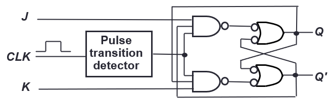
J-K Flip-flop
- Same as SR flip flop, but if both are high, the state toggles
| J | K | CLK | Q(t+1) |
|---|---|---|---|
| 0 | 0 | Q(t) | |
| 0 | 1 | 0 | |
| 1 | 0 | 1 | |
| 1 | 1 | Q(t)’ |
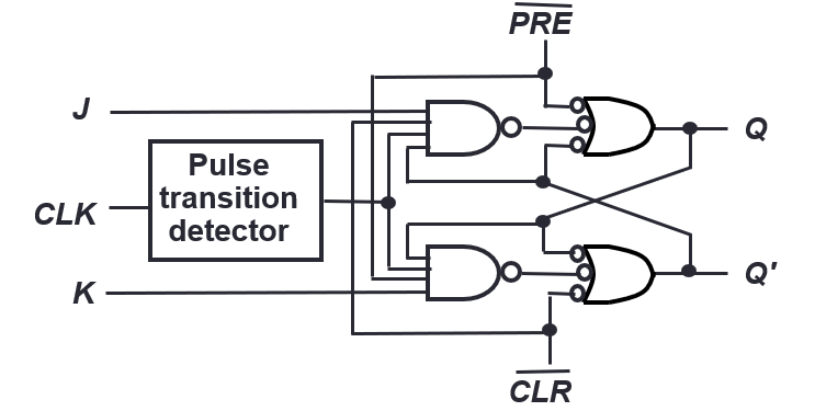
J-K Flip-flop with asynchronous inputs
Preset and clear are active low here:
T Flip-flop
- High input causes output to toggle
- JK flipflop but J and K are connected together to form T
| T | CLK | Q(t+1) |
|---|---|---|
| 0 | Q(t) | |
| 1 | Q(t)’ |
Circuit Analysis
- Steps
- Derive state equations & output function
- Draw state table: m flip-flops and n-inputs → rows
- Draw state diagram: each flip-flop value represents a state, so up to states
- and denote the present state and next state of flip-flop
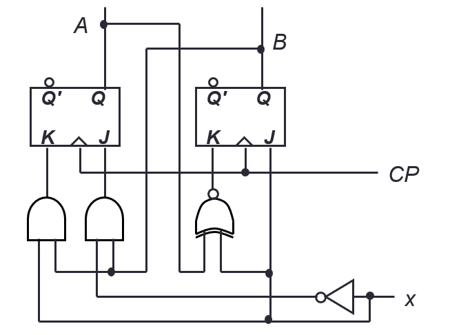
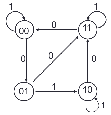
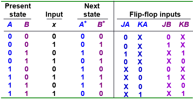
Example
Input functions
- JA=B
- KA=B.x’
- JB=x’
- KB=A’.x + A.x’
Fill state table
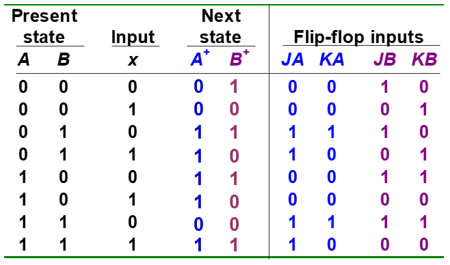
Draw state diagram
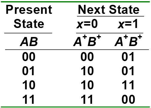
Circuit Design
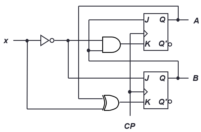
Example
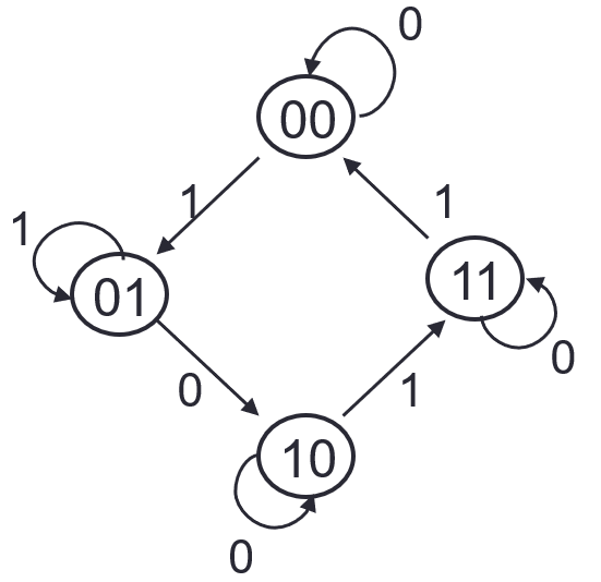
State Table
Derive flip-flop input functions
- Use k-maps to simplify
- JA=B.x’
- JB=x
- KB=(A xor x)’
- KA=B.x
- If there are unused states (not in state diagram) all columns of state table can be X
- If outputs are required, need to create simplified expression for them also
Draw Circuit Diagram