Gate-level design
- Determine inputs/outputs
- Truth table
- Simplify (can use k-maps)
- Implement using logic gates
Examples
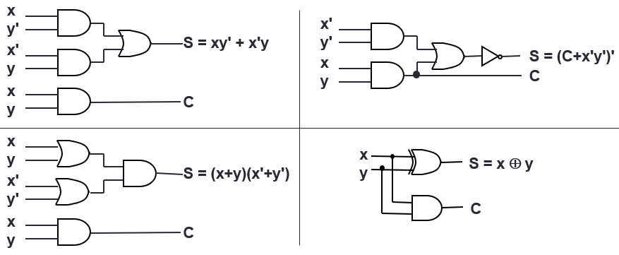
Half Adder
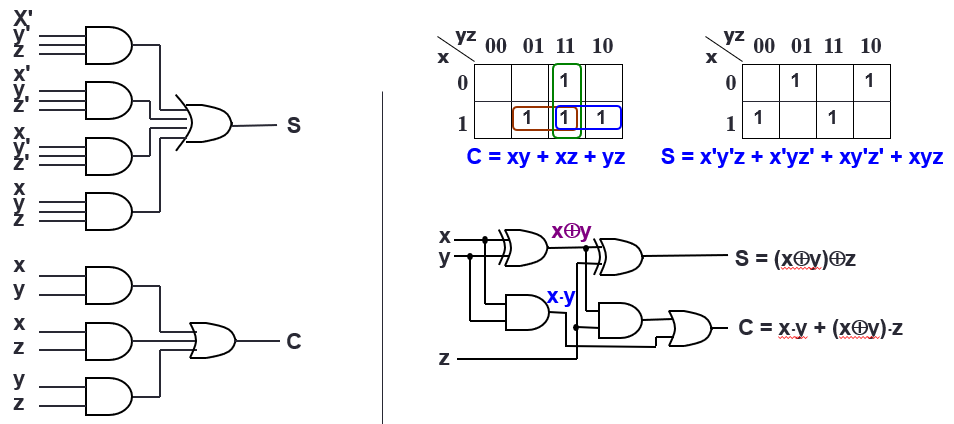
Full Adder
| A | B | Cin | Cout | S |
|---|
| 0 | 0 | 0 | 0 | 0 |
| 0 | 0 | 1 | 0 | 1 |
| 0 | 1 | 0 | 0 | 1 |
| 0 | 1 | 1 | 1 | 0 |
| 1 | 0 | 0 | 0 | 1 |
| 1 | 0 | 1 | 1 | 0 |
| 1 | 1 | 0 | 1 | 0 |
| 1 | 1 | 1 | 1 | 1 |
Block-level design
MSI Components (med scale integration)
Decoder
- Based on the input bits, the decoder makes one of the outputs high
- n-bit decoder can have up to 2n outputs
- Any combinational circuit with n inputs and m outputs can be implemented with an n:2n decoder with m OR gates.
- Use when circuit has many outputs, and each function is expressed with a few minterms
- Use decoder to generate minterms, then OR gates to form the sum
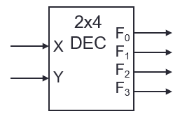
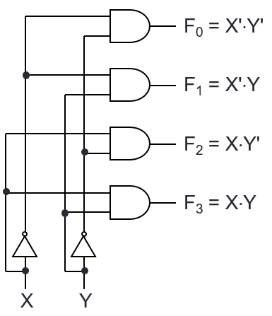
| X | Y | F0 | F1 | F2 | F3 |
|---|
| 0 | 0 | 1 | 0 | 0 | 0 |
| 0 | 1 | 0 | 1 | 0 | 0 |
| 1 | 0 | 0 | 0 | 1 | 0 |
| 1 | 1 | 0 | 0 | 0 | 1 |
Encoder
- Based on up to 2n input bits (of which exactly one is high), encode to n outputs
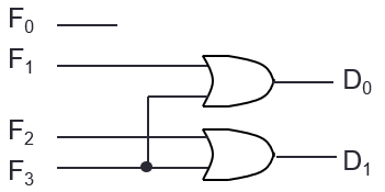
| F0 | F1 | F2 | F3 | D1 | D0 |
|---|
| 1 | 0 | 0 | 0 | 0 | 0 |
| 0 | 1 | 0 | 0 | 0 | 1 |
| 0 | 0 | 1 | 0 | 1 | 0 |
| 0 | 0 | 0 | 1 | 1 | 1 |
| the | rest | | | X | X |
Priority Encoder
- If more than one input is high, take the highest priority one
- If all inputs are zero, it is invalid (V=0)
| F0 | F1 | F2 | F3 | D1 | D0 | V |
|---|
| 0 | 0 | 0 | 0 | X | X | 0 |
| 1 | 0 | 0 | 0 | 0 | 0 | 1 |
| X | 1 | 0 | 0 | 0 | 1 | 1 |
| X | X | 1 | 0 | 1 | 0 | 1 |
| X | X | X | 1 | 1 | 1 | 1 |
Demultiplexer
- Depending on the input from select lines, data is “routed” to one of the outputs
- Identical to a decoder with enable
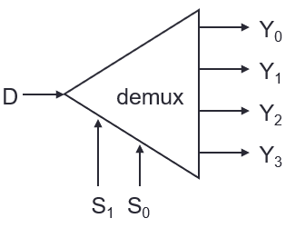
| S1 | S0 | Y0 | Y1 | Y2 | Y3 |
|---|
| 0 | 0 | D | 0 | 0 | 0 |
| 0 | 1 | 0 | D | 0 | 0 |
| 1 | 0 | 0 | 0 | D | 0 |
| 1 | 1 | 0 | 0 | 0 | D |
Multiplexer
- “routes” one of up to 2n input bits to one output bit
- Multiplexers can be combined to make bigger multiplexer (e.g. 2 4-bit multiplexers combined using one 2-bit multiplexer)
- Implementing a function with n-bit input
- n-bit (2n to one) multiplexer: put 1 on the input if the minterm is 1, 0 otherwise
- (n-1)-bit multiplexer: put either 1, 0, A or A’ where A is the last input bit
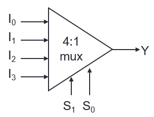
| S1 | S0 | Y |
|---|
| 0 | 0 | I0 |
| 0 | 1 | I1 |
| 1 | 0 | I2 |
| 1 | 1 | I3 |
Calculating Delay
- Consider a logic gate with delay t. The time that the outputs become stable is the latest time the input becomes stable + t