Datapath
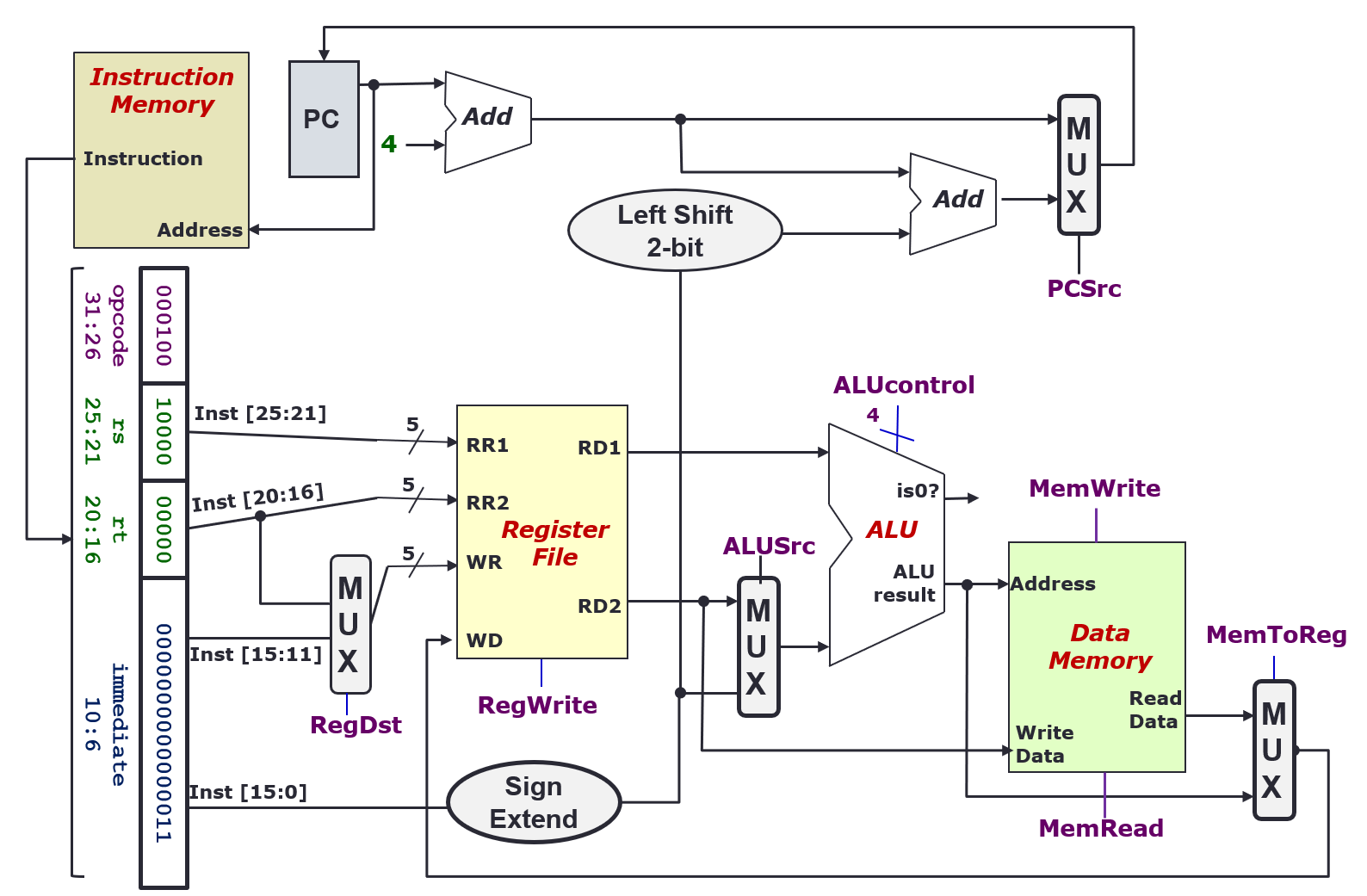
- Collection of components that process data
- Performs arithmetic, logical and memory operations
Instruction Execution Cycle
- Fetch: Get instruction from memory (address is in PC register)
- Decode: Find out the operation required
- Operand Fetch: Get operands needed for operation
- Execute: Perform the required operation
- Result Write (Store): Store the result of the operation
- Next Instruction: back to fetch
Fetch Stage
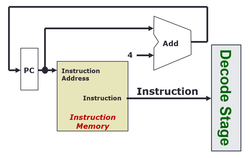
- Every clock cycle, the PC register is updated, with +4 every rising clock edge
- The Instruction Memory takes in the instruction address from the PC, and outputs an instruction
Decode Stage
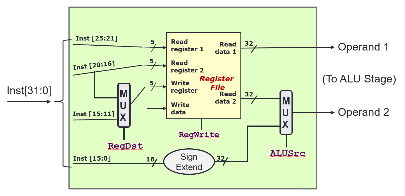
- The instruction is broken down to its constituent parts
- The Register File
- Takes in
Read registernumbers, and outputs the data that the registers contain - Takes in
Write registernumbers, and writesWrite datato it
- Takes in
RegWriteis a control signal that indicates whether to write the data toWrite register: 1(True) = write, 0 (False) = no write- Handling different instruction types
- R format:
RegDest = 1,ALUSrc = 0- Inst[25:21] (rs) →
Read register 1 - Inst[20:16] (rt) →
Read register 2 - Inst[15:11] (rd) →
Write register
- Inst[25:21] (rs) →
- I format:
RegDest = 0,ALUSrc = 1- Inst[25:21] (rs) →
Read register 1 - Inst[20:16] (rt) →
Write register - Inst[15:0] (Immd) →
Operand 2
- Inst[25:21] (rs) →
-
J format:
RegDest =,ALUSrc = ?
- R format:
- Multiplexer
- n-bit control signal, will chose from inputs, to produce one output
ALU Stage or Execution Stage
- Arithmetic (
add,subetc.), Shifting (slletc.), Logical (andetc.) - Memory address calculation (
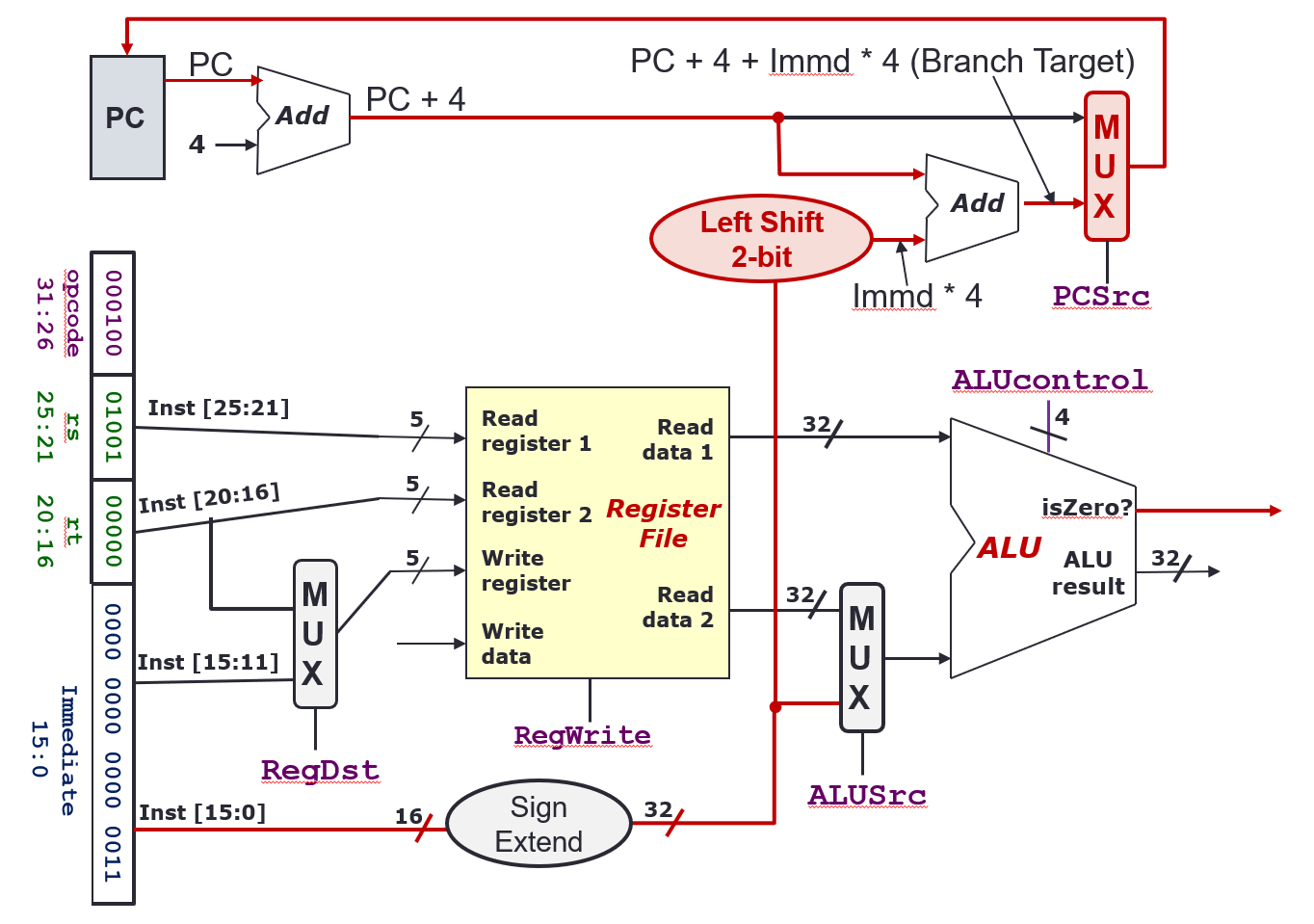
lw,sw, etc.) - Branch operation (
bneetc.): Register comparison and target address calculationALUSrc = 0for ALU to decide whether to branchPCSrc = 1so that PC will be updated with branch target
- Outputs
ALU result:A op BisZero?:(A op B) == 0
ALUcontrol4 bit control signal0000: AND0001: OR0010: add0110: subtract0111: slt1100: NOR
PCSrc1 bit control signal, decides whether to update PC withPC + 4orPC + 4 + Immd * 4(Whether to go to the branch target or not)
Memory Stage
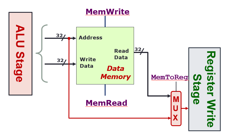
- Only load and store instructions perform operations in this stage
Address: 32 bits, contains the address to read/write toWrite Data: 32 bits, contains the data to writeRead Data: 32 bits, contains the data that has been readMemWrite: When true, the data onWriteDatawill be written to the addressAddressMemRead: When true, the data at addressAddresswill be output atReadData- Only one of
MemReadorMemWritecan be asserted (true) at any time, both 0 means don’t do anything MemToReg: When 0, send the output of the memory stage to the next Result Write stage. When 1, send the output of the ALU directly
Register Write Stage
- Output of memory stage is just put back into the register file
WriteData RegWritecontrol whether to write the data or not
Examples
add $rd, $rs, $rt
- Fetch: Read instruction from PC
- Decode/Operand Fetch: Read
$rsas opr1, read$rtas opr2 - Execute (ALU): Result = opr1 + opr2
- Execute (Memory Access): –
- Result Write: Result stored in
$rdlw $rt, ofst($rs) - Fetch: Read instruction from PC
- Decode/Operand Fetch: Read
$rsas opr1, useofstas opr2 - Execute (ALU): MemAddr = opr1 + opr2
- Execute (Memory Access): Use MemAddr to read from memory
- Result Write: Memory data stored in
$rt`beq rt, ofst“ - Fetch: Read instruction from PC
- Decode/Operand Fetch: Read
$rsas opr1, read$rtas opr2 - Execute (ALU): Taken = (opr1 == opr2) ?, Target = (PC + 4) + ofst * 4
- Execute (Memory Access): –
- Result Write: If (Taken), PC = Target
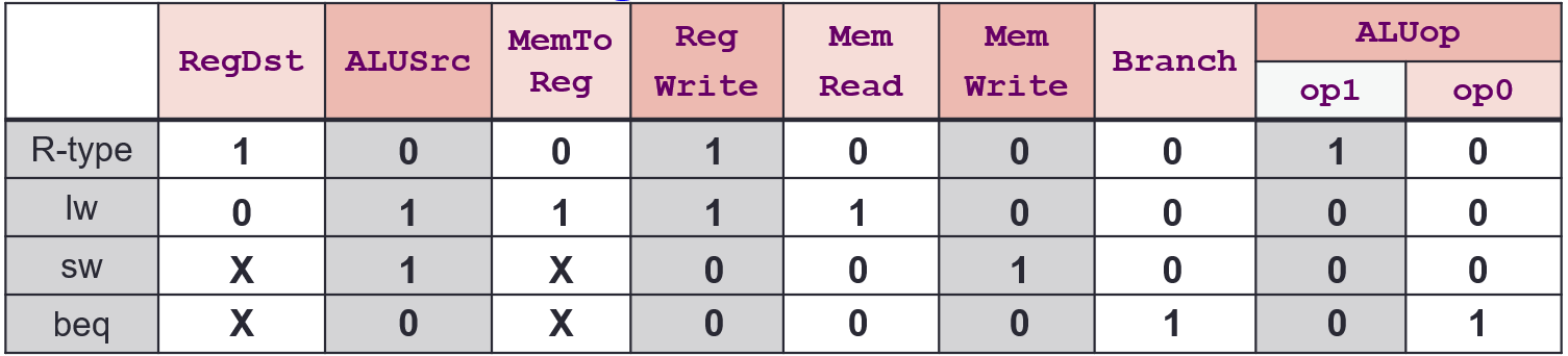
Control
- Tells the datapath, memory and IO devices what to do according to program instructions
Control Signals
| Signal | Purpose |
|---|---|
RegDst | writeRegister → 0: Inst[20:16]; 1: Inst[15:11] |
RegWrite | 0: No register write; 1: Write new value |
ALUSrc | ALU Input → 0: Registers 1: Immd |
MemRead | 0: Don’t read; 1: Read Data Memory |
MemWrite | 0: Don’t write; 1: Write to Memory |
MemToReg | Reg write data → 0: ALU Result; 1: MemRead Data |
PCSrc | 0: PC = PC + 4; 1: Jump to calculated position |
ALUCtrl | What operation the ALU does (see above) |
PCSrc = Branch AND isZeroBranchis a Control output, whether the instruction needs to branch or notisZerois an ALU output, whether the comparison should result in a branch
ALUCtrl
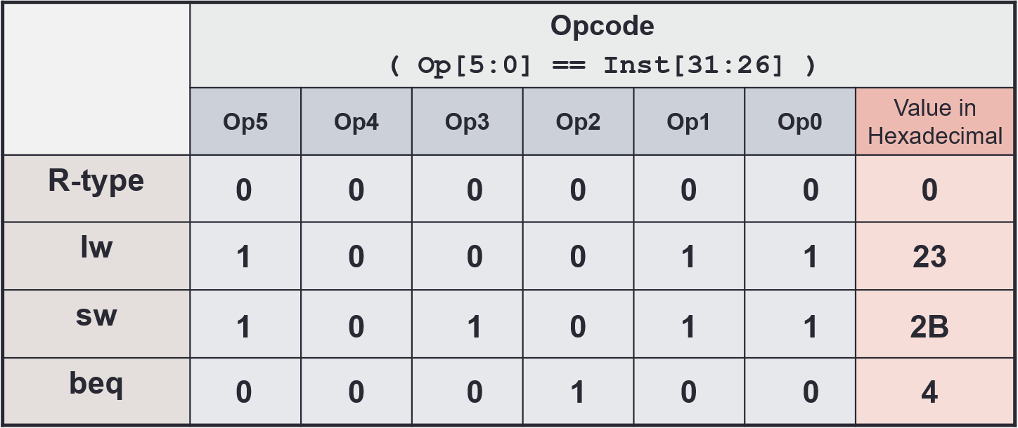
ALUop(2 bit) is generated using the opcode only, by the Control
| Instruction Type | ALUop |
|---|---|
lw/sw | 00 |
beq | 01 |
R-type | 10 |
ALUControl(4 bit) is generated usingALUopandfunct, by the ALU Control- If
ALUopis 00 or 01, thefunctfield is ignored,ALUCtrlis generated directly ALUControlis made ofAinvert,Binvertandop(different fromALUop)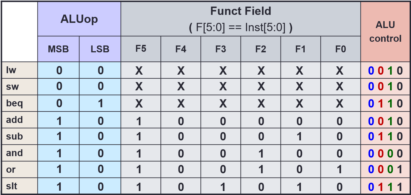
- If
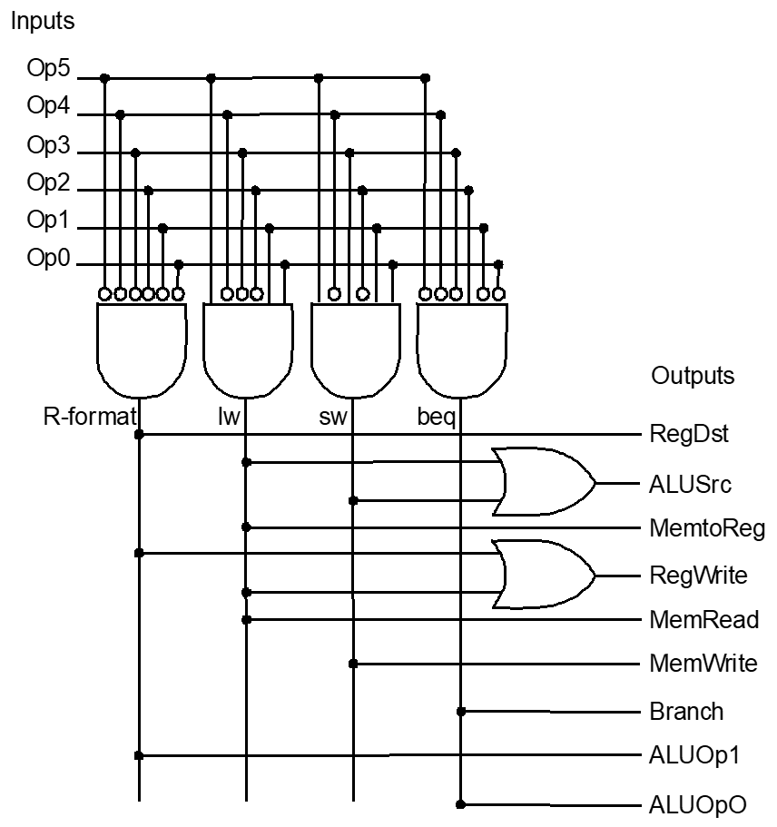
Control Logic
Outputs
Inputs
Implementation
ALU
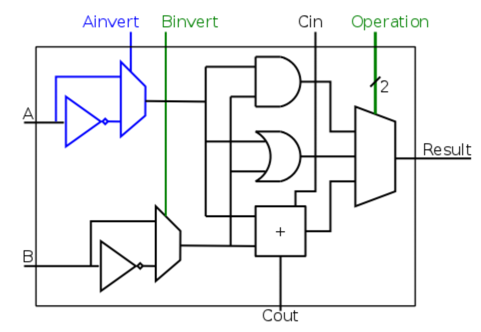
- ALU is made of many cells, with
Coutconnected toCin
Ainv | Binv | Op | Function |
|---|---|---|---|
| 0 | 0 | 00 | AND |
| 0 | 0 | 01 | OR |
| 0 | 0 | 10 | add |
| 0 | 1 | 10 | subtract |
| 0 | 1 | 11 | slt (not implement in diagram) |
| 1 | 1 | 00 | NOR |